General Settings
Width
The width of the cabinet from the outside of the left side to the outside of the right side.
Depth
The depth of the cabinet without front.
Deep page left right
Determines the bevel of the cabinet type front diagonally over the depth of the two sides right and left. It is also possible to enter a value and a number of degrees. To do this, the degree sign ° must be used.
Example: Deep side left right: 330 20°
Creates a cabinet with a side depth of 330mm on the left. The depth of the right side is calculated from the angle and the cabinet width.
Sloping roof L ̄ | R ̄ |
Determines the bevel left and right over two pairs of values. A pair of values consists of the chamfer at the top (measured horizontally) and laterally (measured vertically). It is also possible to enter a value and a number of degrees. To do this, the degree sign ° must be used.
Example: Sloping roof L ̄ | R ̄ |: 20° 100 0 0
Creates a bevel at the top left starting on the left side 100mm below the cabinet height with a 20° slope running upwards.
Segment Settings
Height segment
A cabinet consists of up to five superimposed segments. The height indicated here always refers to the middle of the intermediate floors. In the first segment at the bottom of the lower floor and at the top of the last segment on the top edge of the upper floor. The lid and base heights contributing to the total height are entered in a separate field.
Simple copying segments
By entering a negative integer, an underlying segment can be copied completely. For example, if you want to copy the values from the Lower segment in segment Center, which is two segments below, you enter in the field Height – 2 .
Expand segment height to total height
Entering a negative measure increases or decreases the height of the segment by the missing value. For example, if you enter the value – 800mm in the height field of the middle down segment for a cabinet with a total height of 740mm ( 600mm in the bottom segment, 140mm in the middle bottom segment), this is extended by 60mm to 200mm.
Grip rotation and positions in the segment
The field consists of two sections.
- A single value for the degree of rotation of the handle
- Multiple values for the position of the handle on a front within a vertical subdivision. Superimposed fronts of a segment (horizontal subdivision) have the same position.
The value for a grip position consists of two characters for the horizontal and vertical position on the front:
- Horizontal positions: Links, Rechts, Mitte and 2 for a double-sided handle left and right
- Vertical positions: Unten, Mitte, Oen
- the n sign does not draw a handle at the position
Example: U Handle Red° Pos LRM2:OMU/N90 RO N LO
The handle is rotated by 90°. The positions for a triple vertical subdivision are from left to right: Top Right, No Handle, and Top Left
Subdivision of a segment
The field consists of three consecutive values
- Vertical division: number of parts next to each other
- Horizontal division: Number of parts on top of each other (no compartments!)
- Middle side (V) or intermediate floor (H) continuous
The vertical division determines the number of compartments separated by center sides. It is irrelevant whether the middle side is also drawn at the position or not. See center side visible field.
The horizontal division distinguishes further intermediate floors. This is primarily intended for further drawers on top of each other in a segment and overlaps with the shelves.
If middle sides and intermediate bottoms exist within a segment, the third parameter indicates which of the two is drawn at the intersection points.
Example: Vertical Horizontal 5 2 V Subdivision
The segment receives five parts next to each other and thus four center sides, as well as two parts on top of each other and thus an intermediate floor. The intermediate floor bumps into the middle sides.
Door stop direction and visibility of the center side
The field is composed of alternating consecutive values for the direction of a door within a segment followed by the visibility of the center side.
Four options are conceivable for the position of the door stop, i.e. the door hinges:
| Position | Sign | Represented as |
|---|---|---|
| Left | L, l, > | > |
| Right | R, r, | < |
| Above | O, o, | O |
| Below | U, u | U |
The visibility or formation of the middle side is regulated here by a control mark:
| Training | Sign | Represented as |
|---|---|---|
| Invisible | n, x, 0 | • |
| Interior | i, ! | ! |
| Normal | j, y, 1 | | |
Example: Stop L/R/O/U MitSei J/N: r j l n o
This sequence of signs means that the first door is struck from the left on the right side. Then a middle side is drawn. The middle door is attached to this center side on the left. The next middle side is missing and the segment ends with a flap hinged at the top.
For a better clarification of the inputs, the following are displayed: Stop L/R/O/U MitSei J/N: • O
Summarizing adjacent fronts
The inner center side is a special case for cross-center fronts. Here, two fronts from adjacent parts can be combined. This summary only takes place with internal (!) or invisible (•) middle sides and also only if the direction of the otherwise adjacent doors would be the same. Stop L/R/O/U MitSei J/N: < ! < |
This sequence of characters means a division of the segment into three parts. The first and second parts are separated by an internal central side. Because the direction of attack in these two parts is on the left, the front is combined there and struck on the left (i.e. on the left side of the body).
The third part is then separated from the first two by a normal middle side and thus a separate door is drawn there, which is also struck on the left.
The distance of the inner center sides can be set segment by segment in the parameter Distance Center Side Front .
Spacing of the middle sides
The field allows the manual division of the middle sides over the cabinet width of a segment. There are two possibilities:
- Equally wide shelves (standard). The available width of all not fixed middle sides is divided so that the compartments have the same clear width.
- Equally wide fronts. Takes effect as soon as the sign = is entered in the field. The available width is evenly distributed taking into account the front joints, so that the fronts become the same width.
Missing information is calculated evenly distributed to the remaining width.
Example of the same fronts: MS clear width (=front/compartment)200 = = 200
This sequence of characters for a four-part vertical subdivision of a Semgent means:
- The distance between the left body side and the center of the first center side is 200mm – as well as the distance between the center of the last center side and the right body side
- The middle side in between is evenly distributed, so that the front width of the second and third doors is the same. With equally distributed front widths, different front joints left, right and vertical are taken into account.
- The number of center pages is defined via the Subdivision field
Example of the same compartments: MS clear width (=front/compartment)200 200 0 0
Since the specification of 0 is counted as a character for the same tray widths, these inputs are then displayed as follows: MS light width (=front/tray)200 200 – –
This sequence of characters for a four-part vertical subdivision of a semgent then means:
- The distance between the left body side and the center of the first center side and then to the center of the second center side is 200mm each
- The following central side is evenly distributed, so that the light of the second and third doors is the same. Different thicknesses of the pages and middle pages are taken into account.
- The number of center pages is defined via the Subdivision field
Classification of shelves
Specifies the number of shelves. A grid (e.g. 32mm) can be used, which is indicated by the character *. The reference point of the grid is the lower edge of the segment floor, which can be an intermediate floor or the lower floor.
Example: Subjects Number Of Abst. >Unten: 2*32
Creates two shelves evenly distributed and moves them to the nearest point of the 32mm grid.
The calculated values are appended to the field Compartments Number Of Abst. >Unten: 2*32 192 384
The first shelf is 192mm, the second 384mm high above the segment floor.
These dimensions indicate the difference in height between the lower edge of the floor of the current segment and the shelf. The heights can also be set manually. Once a grid has been defined, the heights entered are aligned and adjusted accordingly. If no grid is desired, the * operator can be omitted. It is then supplemented in the form 2*0.
Other parameters
Base height
The height of the base up to the lower edge of the lower floor. The base height is included in the total height.
Base position
If the socket type has a foot or symbol set. Can the positions at which a footer is inserted be specified here.
The possible positions are values or compound values from the characters Links, Rechts, Vorne, Hinten and Mitte.
Example: Socket position L R V H (+M): L LM H HM
This combination creates feet on:
- L: Left front and rear
- LM: Left Center
- H: Rear right and left (where left would already be covered by L )
- HM: Rear center
Socket Bounce Back
The field is composed of four values for the return of the base left, right, front and back perpendicular to the outside of the body.
For example, if the first value is 30mm, the bases at the left positions (L or LV, LH and LM) are indented by 30mm from the left side of the body.
Socket Thickness
The field consists of four values for the thickness of the base or aperture left, right, front and back.
For example, if the first value (left) is 90mm, and the third value (front) is 60mm. Thus, one foot at the left front position will be 90mm wide and 60mm deep. An aperture at the front would be 60mm thick.
Lid Thickness / Chamfer
The field consists of three values for the thickness of the lid and, if necessary, the strength of a chamfer at the top and bottom. The chamfer is only taken into account for the lid types rounded or chamfered .
A value combination of 45 8 0 would achieve a lid thickness of 45mm and a chamfer of 8mm at the top of the lid type.
Lid protrusion
The field consists of four values for the protrusion of the lid on the left, right, front, and back sides
A value combination 30 15 15 0 would protrude the lid at the front by 30mm and left and right by 15mm and let the rear body flush.
Lid Object
Here the name of a symbol can be entered, which then appears on the lid. The position and dimension can then be set with the parameter Position and Dimension of the lid object .
Position and dimension of the lid object
Allows you to specify a position via coordination X and Y and the width of the symbol
- Pos X – position in x direction (width) starting from the left side of the cabinet
- Pos Y – position in the y direction (depth) starting from the front of the cabinet
- Width – Dimension in the x-direction of the symbol. This is scaled symmetrically in all three dimensions with the same factor.
Cover Bar Height / Thickness
Here, the height and thickness of the cover bar can be set with two consecutive values. It is drawn on the lid at the back edge and in the width of the lid
Top view in 2D plan
If this checkbox is activated, the cabinet is drawn in a simplified two-dimensional representation in the “2D Plan” view.
Front Parameters
Type of stop and bevel of the front per segment
Determines the type of stop of a door within a segment and whether it is beveled or straight drawn in an inclined cabinet. it is a multifield with five spaces-separated values for each segment u to o
The type of stop is entered with the following characters:
- a – Impactful
- g – Striking and not beveled (gerade)
- s – Intermediate, with pages visible
- b – Intermediate, with sides and floors visible
- m – Intermediate, with pages and center pages visible
- z – Intermediate, with intermediate floors visible
In the case of an inclined cabinet, the fronts are automatically bevelled, unless the stop type g is specified. Intermediate beats are always bevelled.
Example: Front stop type/abschrg U->Og s s s s s
This sequence of characters means that in segment U the front is drawn open and straight. The overlying segments are all intersecting and bevelled (if it is an inclined cabinet).
The field also complements itself automatically. If you enter e.g. mb , all fronts of the segments are drawn intersecting with visible middle sides and floors. The field is supplemented as follows: Front Anschlagart/Abschrg U-Obm> bm bm bm bm
Front Strength
Here, the strength of the front can be set with successive values for each segment from bottom to top. The value also applies to several fronts within a segment created by a horizontal or vertical subdivision.
Front Joint
Here, the joints (left, right, top, bottom as well as horizontal and vertical) of a front can be adjusted with successive values. Left, right, top and bottom refer to the joint to the outside of the body. The value for horizontal and vertical defines the joint dimension of the front between two above/next to each other fronts. On top of each other (horizontally) then also across segments.
Front front spacing
Here, the distance of the front to the front of the body can be set with successive values for each segment from bottom to top. Opening doors move forward, interlocking doors further to the rear.
Addition to the front joint horizontally
Here, with successive values for each segment from bottom to top, an addition to the width of the joints on the left and right side of the front can be set. A positive value here means an addition to the joint or a dimension, a negative value thus increases the front.
If the value is not explicitly marked for left or right, it is halved and split. This explicit assignment is made with the control characters U and O for bottom and top. No space may be used within the composite value of a segment.
Example:
Front addition horizontal U->O20 L20 R20 R-20 L20R-30This sequence of characters means that in the segment …
- Below the front a total dimension of 20, i.e. divided 10 on the left and right side
- Middle Bottom a dimension of the side of 20
- Center center a dimension of the right side of 20
- Center Top an addition of 20 on the right side
- Above a dimension of 20 on the left and an addition of 30 on the right side
has.
Addition to the front joint vertically
Here, with successive values for each segment from bottom to top, an addition to the width of the adjacent joints above and below the front can be set. A positive value here means an addition to the joint or a dimension, a negative value thus increases the front.
If the value is not explicitly marked for Top or Bottom, it is halved and split. The explicit assignment works as with the horizontal front joint, only with the control characters U and O for bottom and top instead of L and R. No space may be used within the composite value of a segment.
Open display of fronts
Fronts can be displayed segment-by-segment open.
This is given as an integer in degrees for doors or in percent for roller blinds and sliding doors.
Example: Front open in percent U->O15 0 0 0 0
This sequence of characters means that in segment U the front is open 15°. For roller blinds or sliding doors, 15% of the door height.
Symbol Name Handle
Here, a symbol name for the handle can be specified with consecutive values for each segment from bottom to top. If several different values are specified, they must be separated by a vertical line.
Distance of the handle to the front horizontally
Here, with consecutive values for each segment from bottom to top, a lateral distance for the handle to the outside of the front can be specified. Whether this is measured from the left or right depends on the grip position .
Distance of the handle to the front vertically
Here, with consecutive values for each segment from bottom to top, a vertical distance for the handle to the outside of the front can be specified. Whether this is measured from above or below depends on the grip position .
Frieze width of the frame door
Here, the width of the frame friezes left, right, top and bottom can be specified with successive values in the front version frame door.
Filling of the frame door
Here, the thickness of the filling in the front version frame door and the distance of the back of the filling from the trailing edge of the frame can be specified with consecutive values.
Fold of the filling of a frame door
Here, the fold height and depth of the filling in the front version frame door can be specified with successive values.
Number of rungs of a frame door
Here, the number of rungs horizontally and vertically as well as the continuous rung in the front version frame door can be specified with three consecutive values. The third character indicates which rung passes through: Vertikal or Horizontal
For the horizontal rungs, it is possible here to specify a value for each rung one after the other, which defines your distance from the lower edge of the front to the center of the rung.
Dimensions of the rungs of a frame door
Here, the width, thickness and distance from the rear of the rungs in the front version frame door can be specified with three consecutive values.
Corpus Parameters
Corner formation of the body sides
Here the corner formation can be set with successive values for the corners left bottom, right bottom, left top, right top. Possible values for this are:
- S – page continuously. Floor bumps into
- B – Floor throughout. Page toasts
- G – Miter between side and floor
- R – Side bottom continuous and extended by the base height (only available at the lower corners)
Page Thickness
Here, the strength of the page on the left and right can be specified with two consecutive values.
Distance of the page
Here, the distance of the sides to the front / back / top and bottom of the body can be adjusted with four consecutive values. The first four values refer to the left side, the rest to the right side.
Draw page left and right
Here you can specify with two consecutive values whether the Linke or Rreal page should be drawn.
Soil thickness
Here, the strength of the soil can be specified with successive values for each soil from the lower soil to the four intermediate floors to the upper soil.
Ground distance front
Here, the distance of the soil to the front of the body can be adjusted with successive values for each floor from the lower floor via the four intermediate floors to the upper floor.
Width of the floor, version as traverse
Here, the width of the floor (in the direction of the cabinet depth) can be adjusted with successive values for each floor from the lower floor via the four intermediate floors to the upper floor. A positive value indicates the absolute soil width. A negative value determines the distance of the floor to the rear to the inside of the rear wall (if any, otherwise the trailing edge of the body) and thus the floor width relative to the back of the body.
Furthermore, with an addition of two letters to the width, it can be determined whether the floor is drawn as a traverse at the front and / or back. The following values are possible:
- Horizontal
- Vertical
- Ndo not draw
An input of 120HV would draw the floor as a traverse horizontally at the front and vertically at the rear with a width of 120.
80NV draws the floor as a traverse only vertically at the rear with a width of 80.
-100 draws the floor with a distance from the back of 100
Thickness of the middle side
Here, the strength of the center sides can be specified with consecutive values for each segment from bottom to top
Distance center side front
Here, the distance of the middle sides to the front of the body can be specified with consecutive values for each segment from bottom to top. If the type of stop of the front is set intersecting and with visible center sides, this value should be 0.
For each segment, two values are specified separated by an I (for the inside). The first value applies to normal middle pages. The second for internal center sides, which are treated in the parameter door stop direction and visibility of the center side and allow cross-center fronts.
Width of the middle side
Here, the width of the center side (in the direction of the cabinet depth) can be set with consecutive values for each segment from bottom to top. A positive value indicates the absolute width. A negative value determines the distance of the middle side to the back to the inside of the back wall (if any, otherwise the trailing edge of the body) and thus the width relative to the back of the body.
Thickness of the shelves
Here, the thickness of the shelves can be specified with consecutive values for each segment from bottom to top
Distance to the bottom of the front floor
Here, the distance of the shelves to the rear of the front can be specified with successive values for each segment from bottom to top.
Width of the shelf
Here, the width of the shelves (in the direction of the cabinet depth) can be set with successive values for each segment from bottom to top. A positive value indicates the absolute width. A negative value determines the distance of the shelf to the rear to the inside of the rear wall (if any, otherwise the trailing edge of the body) and thus the width relative to the back of the body.
Thickness of the intermediate floors within a segment
Here, the thickness of the intermediate bottoms within this segment can be specified with consecutive values for each segment from bottom to top
Distance of the intermediate floors within a segment to the front
Here, successive values for each segment from bottom to top can be used to specify the distance of the intermediate floors within this segment to the front. If the type of stop of the front is set intermittently and with visible intermediate floors, the distance refers to the front edge of the body and should be 0.
Width of the intermediate floors within a segment
Here, the width of the intermediate shelves within this segment (in the direction of the cabinet depth) can be set with consecutive values for each segment from bottom to top. A positive value indicates the absolute width. A negative value determines the distance of the shelf to the rear to the inside of the rear wall (if any, otherwise the trailing edge of the body) and thus the width relative to the back of the body.
Continuous central sides on the floors
Allows, among other things, continuous center pages. For each floor (lower floor to upper floor with intermediate floors) it can be indicated with a letter whether:
- B – pass through the soils
- M – run through the middle sides
- Z – the floors run through except for collapsible middle sides
Joinable center sides are in two superimposed segments in the same position.
In the case of the lower and upper bottoms, Z only allows the middle sides to pass through, which are already continuous above and below the segment, respectively.

Drawer Parameters
Thickness of drawer parts
Here, the strength of the left, the right drawer side, the front, the rear piece and the drawer bottom can be specified with consecutive values.
Height of drawer parts
Here, the height of the left, the right drawer side, the front and the rear piece in the respective segment can be specified with successive values.
Air of the drawer parts below
Here, the distance of the left, the right drawer side, the front, the rear piece and the drawer bottom from the upper edge of the body floor in the respective segment can be specified with successive values.
Air of the drawer parts front
Here, the distance of the left/right drawer side to the left/right body side and the front piece to the inside of the front can be specified with consecutive values.
Groove depth of the drawer parts
Here, the groove depth of the drawer bottom on the left, right drawer side and on the front/rear piece can be specified with successive values.
Thrust depth of the drawers
Here, the depth of the drawers can be adjusted with successive values for each segment from bottom to top. A positive value indicates the absolute depth. A negative value determines the distance of the drawer to the rear to the inside of the rear wall (if any, otherwise the trailing edge of the body) and thus the depth relative to the back of the body.
Addition of drawer parts
Here, successive values can be used to specify an addition to the BOM for spring-loaded, zinced drawers in the following order:
- Front piece, the value is divided into a left and right addition
- Rear piece, the value is divided into a left and right addition
- Side left, addition front
- Side left, addition rear
- Side right, addition front
- Side right, addition rear
Configuration of a frame guide system
In this area, it is possible to assign settings for a frame guide system (ZFS). The name of this ZFS should match an element CAM drill pattern name for a ZFS.
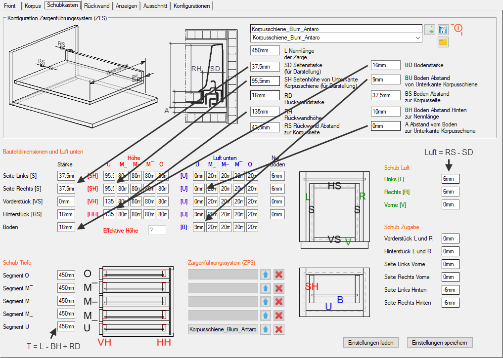
The configuration in the upper area does not take effect until it is used for min. a segment has been adopted in the Frame Guidance System settings in the lower area. The ZFS is not drawn in the original, but the drawer is displayed for an exact position of the holes.
The button  to select a drill pattern name assigns a ZFS name for a drill pattern existing in Elements CAM . Under this name, a configuration file is then looked up to see if it exists and then its values are transferred to the dialog. However, any other name can also be used for the configuration.
By default, the configuration file with the entries of the frame guide systems System Extract.csv is located in the folder:C:\Users\Public\Documents\ElementsCAD\Configurations\Drawer
With the button  to save the ZFS, an entry of the current configuration is then stored in the configuration file.
Example Blum Antaro:
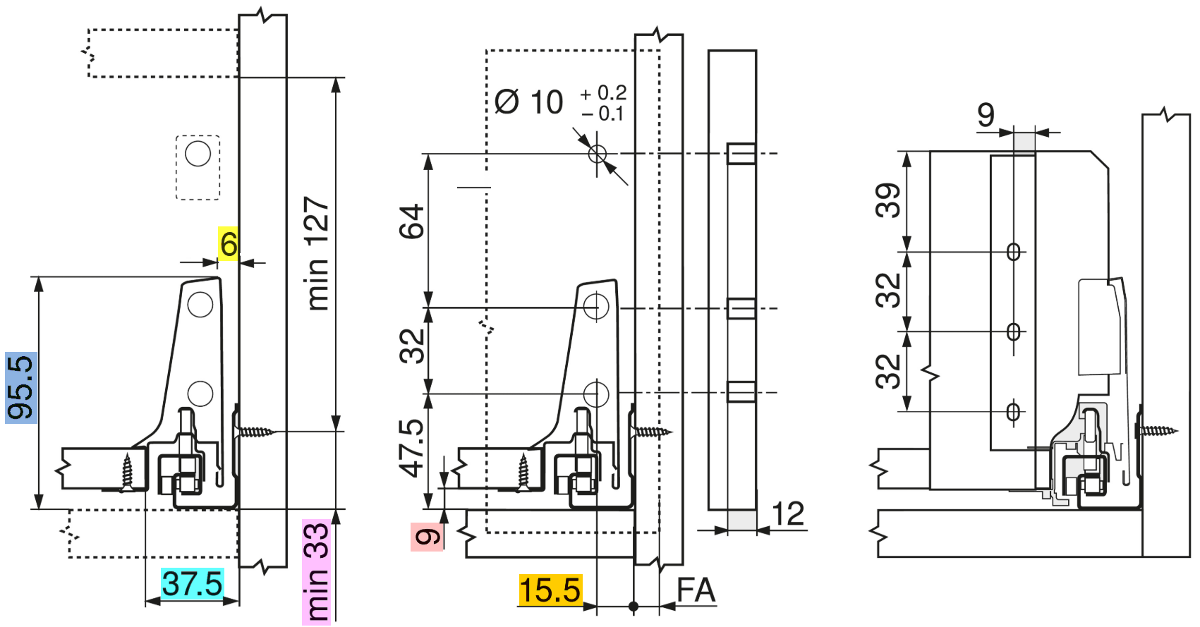

For on the one hand the display and on the other hand the correct export of the drilling patterns, the parameters of the page are adjusted as follows:Page thickness SDThe drilling patterns supplied in ElementsCAD take into account a distance of 6mm from the inside of the body to the outside of the drawer. In the illustration, the rear wall bluntly bumps into the inside of the drawer side. The measure for the cutting of the rear wall is clear width between the inside of the body minus 87mm. This results in 43.5mm from the inside of the drawer side to the inside of the body. If you subtract the 6mm assumed air here, this results in 37.5mm for the side thickness of the drawer side.Side height SHThe side height of the lower edge Body rail is 95.5mmBack wall thickness RDThe plate thickness for cutting the rear wall is 16mmBack wall height RHThe rear wall height is 135mmBack wall Distance to the body side RSAs determined with the side thickness, the distance of the rear wall to the inside of the body is 87mm / 2 = 43.5mmFloor thickness BDEbenso as for the rear wall thickness, the distance of the rear wall to the inside is 87mm / 2 = 43.5mmFloor thickness BDEbenso as for the rear wall thickness the Panel thickness for cutting the floor 16mmFloor distance BUThe floor distance from the lower edge of the body rail is 9mmFloor distance to the body side BSThe floor distance to the inside of the body is 37.5mmFloor distance to the nominal length BHThe floor distance from the lower edge of the body rail is 24mmRefence from the bottom of the bottom of the body rail to the lower edge of the body rail AThe distance of the lower edge of the body rail to the floor below is at least 0mm, i.e. the rail rests on the body floor. The value results from the minimum distance of the screw connection of the body rail of 33mm and the vertical position of the bore of the drill pattern for the Blum Antaro body rail at 33mm: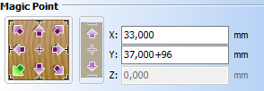 The Y value here refers to the horizontal position of the second body rail hole from the front in the body side.
Distance of the bore for the front attachment to the drawer sideIn consideration of the above information, the drill pattern of the front attachment, which refers to the outside of the drawer sides, results in a dimension of 15.5mm – 6mm = 9.5mm: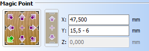 The X-value of 47.5mm here is the vertical distance of the hole for the front attachment to the lower edge of the body rail (see side height)
Assigning the Frame Guide System
Here, the configuration created in the upper area can be transferred segmentally via a button for the ZFS name. The values are then entered appropriately in the lower area, so that the drawer is displayed for an exact position of the holes. (Note: The button is only active if there is also a drawer in the respective segment.)
The button with the arrow upwards, on the other hand, transfers the configuration of a segment to the upper area in the opposite way
The button with the red X removes the assignment to a ZFS name from the segment. However, the values of the drawer remain unchanged.
Rear panel parameters
Thickness of the rear wall and distance from the rear
Here, the cabinet-wide the thickness of the rear wall and then with consecutive values for each segment from bottom to top the distance of the back wall from the trailing edge of the body can be adjusted.
With the last of the six values in this field one can also influence the formation of the backwall groove. The value 1 creates continuous grooves on (middle) sides, in this case no insertion milling (value 0) is generated.
Groove depth of the rear wall
Here, the groove depth of the rear wall can be specified with successive values in the following order:
- Left – Groove depth to the left side
- Right – Groove depth to the right side
- Top – Groove depth to the upper bottom
- Bottom – Groove depth to the lower bottom
- Horizontal – groove depth to the intermediate floors (cabinet-wide)
- Vertical – groove depth to the center sides (cabinet-wide)
- As a fold – value 1: The formation of a groove as a fold is no longer dependent on the groove depth.
Air in the rear wall Groove distance from rear
Here, with successive values, the air to the rear wall in the groove can be specified in the following order:
- Left – Air to left side
- Right – air to the right side
- Above – air to the upper floor
- Below – air to the lower floor
- Horizontal – air to the intermediate floors (cabinet-wide)
- Vertical – air to the center sides (cabinet-wide)
90° corner cabinet parameters
It is possible to create a corner cabinet via the Field Cabinet Type . A second cabinet is added to the main cabinet rotated by 90° (base cabinet). Both cabinets have the full list of parameters and can therefore be individually adapted.
90 ° corner cabinet assignment via ID
ID Cabinet Right A83
This field is automatically pre-populated when selecting the cabinet type as a corner cabinet. Here, for example, with the ID of the base cabinet A83
If you enter the sign ‘-‘, an existing cabinet can be removed.
With the character ‘+’, a cabinet is created and rotated by 90° and added to the existing one.
It is also possible to use an existing cabinet as a counterpart by entering its elements ID (or object name) in the field.
Define aperture for a 90° corner cabinet
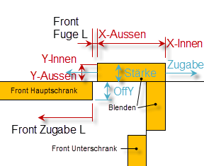
For the main and base cabinet of a corner cabinet, an aperture can be defined on the left and right. The position and size are defined as follows:
- Width (X-inside): In relation to the position of the bezel of the adjacent cabinet
- Width (X-outside): In relation to the door front plus the front joint links or Right
- Thickness (Y-outside): From the front edge of the strongest door front of all segments
- Strength (Y-inside): … up to the strength of the aperture
- Height (Z-Bottom): From the lower edge of the lowest door front
- Height (Z-Top): Up to the upper edge of the top door front
Aperture Strength Addition OffY: 19 0 0 19
The parameter Aperture Strength Train OffY now influences these dimensions of the aperture:
- Thickness: Moves end-Y
- Train: Two values for addition to the calculated width (X-inside) and (X-outside)
- OffY: Shifts (offset) the aperture and thus (Y-outside)
The width (X-outside) can also be influenced horizontally indirectly via a front addition. Here, the end of the aperture changes and thus its width analogous to the beginning of the front.
Example: Aperture Strength Addition OffY: 30 50 19
Creates an aperture with
- Aperture thickness: 30mm
- Overlap of aperture and front: 50mm – thickness of the front joint vertical left or left. Right
- 19mm offset to front edge: 19mm
Define rear bezel for a 90° corner cabinet
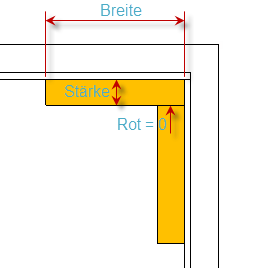
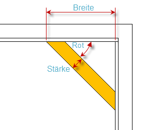
Bezel Rear Strength Width Red°: 19 80 0
Depending on the setting of the red parameter, the rear panel can be built in two parts or one-piece and obliquely:
- Red 0: Two-piece and the bezel of the corner cabinet bumps into the bezel of the base cabinet

- Red 90: Two-piece and the bezel of the base cabinet bumps into the bezel of the corner cabinet
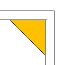
- Red between 0° and 90°: One-piece, diagonally over corner

If you set the strength to 0, a bar is built to the corner
- With width 0, the aperture can ultimately be switched off
Row cabinet parameters
Row cabinet option
If you activate the checkbox in the appropriate place, the cabinet is prepared there for use in a row cabinet. In particular, the thickness of the side or the floor is halved there so that it can be combined with the side or bottom of another cabinet.

